Growing the 6502 emulator.
In a previous post, I talked about the 6502 emulator I write. I teased it might be expanded into an emulator of an existing computer. It’s been - checks notes - two years since that post, and a lot of things have happened. For one reason or another, I just never wrote a post about. Well, that’s going to change today.
First question: which computer are we going to emulate? An ideal first target computer would be a system without any custom, proprietary, integrated circuits. The early Commodore PET fits this bill perfectly. In addition to the 6502 processor it has two 6520 Peripheral Interface Adapters (PIA), a 6522 Versatile Interface Adapter (VIA), some ROM and RAM chips and a bunch of 74-family logic chips. The PIAs and the VIA are I/O port controllers to handle communications with external peripherals. Later models integrated a bunch of logic chips into a custom CRT controller chip, but the 2001N model predates this.
Second question: what are we trying to accomplish with writing this emulator? I don’t want to compete with the excellent emulators already out there. That would be silly. My goal hasn’t changed, I want to use the process of developing the emulator to further my understanding of the inner workings of digital circuits. I want to be able to examine the state of each signal in the computer at every clock cycle. So that’s what we’re going to do. Dig up the circuit diagram of the computer, and define and simulate each connection.
A ‘minimal’ 6502 based system
Emulating the full PET still felt a little daunting. Going step-by-step seemed a much wiser approach. We already have a test bed with a 6502 and generalized ROM and RAM components. First, we add a 6520 PIA chip. Then a small 16x2 character LCD and finally a keypad. And we end up with a computer that can take user input and display some output. Nice.
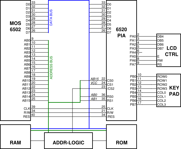
The 6520 emulation was developed the same way as the 6502. Read the data sheet, implement a piece, and verify the behavior with a unit test. Rinse and repeat. After that was finished, the 6520 was integrated in to the test bed and another unit-test was added that checks if the internal registers of the 6520 can be changed by the 6502. Progress!
Next up, the LCD. The Hitachi HD44780 is a popular LCD controller, making it the obvious choice to implement. Only the part of the controller facing the computer is emulated in full detail. The part driving the LCD is emulated on a higher, more abstracted level.
The keypad uses a straightforward matrix construction. It is scanned row by row; pressing a key grounds the corresponding column.
All this exposed a few issues with the 6520 implementation that weren’t covered in the unit tests (yet). But all in all, this part went rather smoothly.
The internals
At this stage the emulator itself isn’t much to talk about. It’s just enough to get the job done. Which is good, because I don’t want to waste resources working on it before I have a good understanding of what the requirements will be.
The emulator has two major components: chips and signals. Chips implement the logic of the integrated circuits, and their interface resembles the pin-layout of the respective ICs. Signals represent the connections between chips. Each connection drawn on the schematic diagram is represented and simulated separately.
The emulator breaks up the execution in discrete time steps, going from clock edge to clock edge. All the signals are double buffered, one buffer is used for reading the current state, the other for writing the new state after this time step. This way the chips can be processed simultaneously while reading from a consistent, non-changing, input state.
The implementation of the emulator has changed a lot since the early version. This will be the subject of a future blog post.
All posts in this series.
- Part 1: I accidentally wrote a 6502 emulator
- Part 2: This post
- Part 3: Dromaius: playing with PETs
- Part 4: Dromaius: the simulator core.